Creating Links
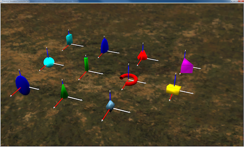
In this tutorial we will create various shapes and add them to a link. The next figure shows eleven different shapes, each with a coordinate system at their origin point.

Eleven example shapes. Coordinate systems are located at the origin of each shape.
1. Create a new package with the name linkExamples
This should have the same folder structure that you used in the Pendulum Example.
Your new linkExamples package should be within your us.ihmc.exampleSimulations package.
2. Add the class LinkExamplesSimulation
Create a new class in the us.ihmc.exampleSimulations.linkExamples package called LinkExamplesSimulation
3. Fill in LinkExamplesSimulation as follows:
The following code is where you will be declaring final variables for shapes like a sphere, ellipsoid, cylinder, arc torus, and wedge.
We typically declare these variables separately than the creation of the shapes so that they can can be more easily changed and found.
The parameters that adjust placement and spacing of the shapes are the OFFSET and COORD_LENGTH.
4. Add a constructor to your LinkExamplesSimulation class
The structure of this code should now be familiar to you. Notice, however, that this is purely a static graphic we are creating. There is no robot, and thus no dynamics.
This will allow us to focus on creating the graphics of a link.
5. Next add the method exampleShapes to your LinkExampleSimulation class
This method will show you examples of how to create simple shapes, assign a color, and add them to your simulation.
In this method there are examples of a Sphere, Ellipsoid, Cylinder, ArcTorus, Extruded Polygon, Mesh Data, and a Gridded Polytope.
6. Add the main method to your class
This method should just simply create a new LinkExamplesSimulation.
Just as follows:
Full code for the class
Link Examples Simulation
